
Therefore, rise and fall times may be approximated by the following: In most cases, a satisfactory estimate of average input current (IG(AV)) can be made from a rudimentary analysis of the drive circuit so thatĭuring the rise and fall time interval when switching a resistive load, VGS remains virtually constant at a level known as the plateau voltage, VSGP. The published capacitance data is difficult to use for calculating rise and fall because drain−gate capacitance varies greatly with applied voltage.

The lengths of various switching intervals (t) are determined by how fast the FET input capacitance can be charged by current from the generator. Switching behavior is most easily modeled and predicted by recognizing that the power MOSFET is charge controlled. Drain−To−Source Leakage Current versus Voltage On−Resistance Variation with Temperatureįigure 6. On−Resistance versus Drain Current and Gate Voltageįigure 5. On−Resistance versus Drain Current and Temperatureįigure 4. (VDS = 48 Vdc, ID = 30 Adc, VGS = 10 Vdc)įigure 3.

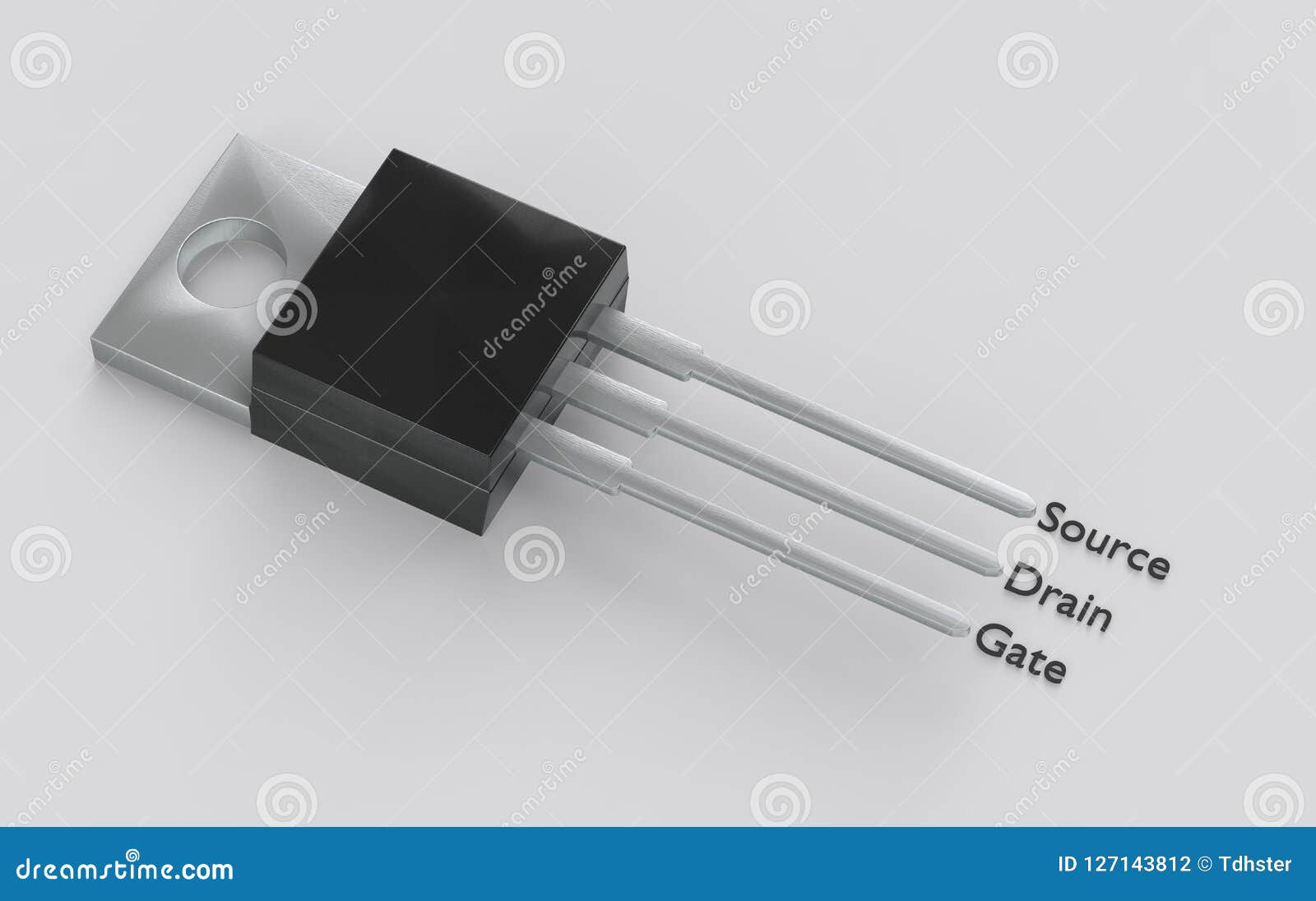
Static Drain−Source On−Resistance (VGS = 10 Vdc, ID = 15 Adc)ĭrain−Source On−Voltage (VGS = 10 Vdc, ID = 30 Adc)įorward Transconductance (VDS = 8.3 Vdc, ID = 15 Adc) Threshold Temperature Coefficient (Negative) Gate−Body Leakage Current (VGS = ± 15 Vdc, VDS = 0 Vdc) Zero Gate Voltage Drain Current (VDS = 60 Vdc, VGS = 0 Vdc) Maximum Lead Temperature for Soldering Purposes, 1/8² from Case for 10 secondsĭrain−Source Breakdown Voltage (VGS = 0 Vdc, ID = 0.25 mAdc) Single Pulse Drain−to−Source Avalanche Energy − Starting TJ = 25☌ Total Power Dissipation TA = 25☌ (Note 1) Total Power Dissipation 25☌ Derate above 25☌ The following figure is the diagram of MTB30P06VT4G pinout. These Devices are Pb−Free and are RoHS Compliant.AEC−Q101 Qualified and PPAP Capable − MTBV30P06V.

IDSS and VDS(on) Specified at Elevated Temperature.Designed for low voltage, high speed switching applications in power supplies, converters and power motor controls, these devices are particularly well suited for bridge circuits where diode speed and commutating safe operating areas are critical and offer additional safety margin against unexpected voltage transients. This Power MOSFET is designed to withstand high energy in the avalanche and commutation modes.


 0 kommentar(er)
